Introduction
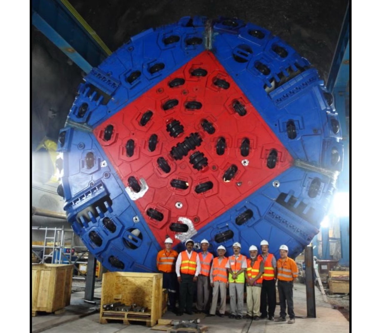
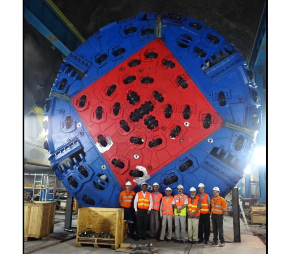
The Neelum-Jhelum Hydroelectric Project, located in Azad Jammu and Kashmir, is a flagship venture under the Pakistan Water and Power Development Authority (WAPDA). It aims to harness hydropower efficiently through advanced engineering techniques. A key component of this project involves the excavation of a twin headrace tunnel spanning 11.5 km, constructed using Tunnel Boring Machines (TBMs). With overburden depths ranging from 1,000 m to 1,900 m, the project necessitates an in-depth understanding of stress distribution and effective rock support design to ensure structural stability and worker safety.
This article delves into the geology, stress analysis, and innovative rock support strategies employed for TBM-driven tunnels, emphasizing findings from the RocSupport and Phase2 modeling programs.
1. Geological Setting
The TBM tunnel alignment passes exclusively through the Murree Formation, characterized by alternating beds of sandstone, siltstone, mudstone, and shale. These lithological units present unique challenges:
- Sandstone (SS1 and SS2): Generally strong and stable, with minimal squeezing tendencies.
- Siltstone: Moderate strength but prone to overstressing at greater depths.
- Mudstone: Weak and highly susceptible to severe squeezing and plastic deformation.
The varying rock types are interbedded, forming complex “sandwiches” that necessitate a flexible and adaptable support design. A geological mapping report prepared by NESPAK serves as the foundational reference for understanding these conditions.
2. Stress Analysis Methodology
The analysis incorporates empirical, analytical, and numerical methods to evaluate tunnel stability under different geological conditions. Two primary tools were employed:
2.1 RocSupport Analysis
RocSupport is a quick and effective program for visualizing tunnel deformation in weak rock. It assumes:
- A hydrostatic in-situ stress field.
- Homogeneous and isotropic rock mass behavior.
- Elastic-perfectly plastic support response.
This program helped establish the initial support design by modeling the interaction between ground reaction curves and support systems for varying rock classes under high overburdens. Key results included:
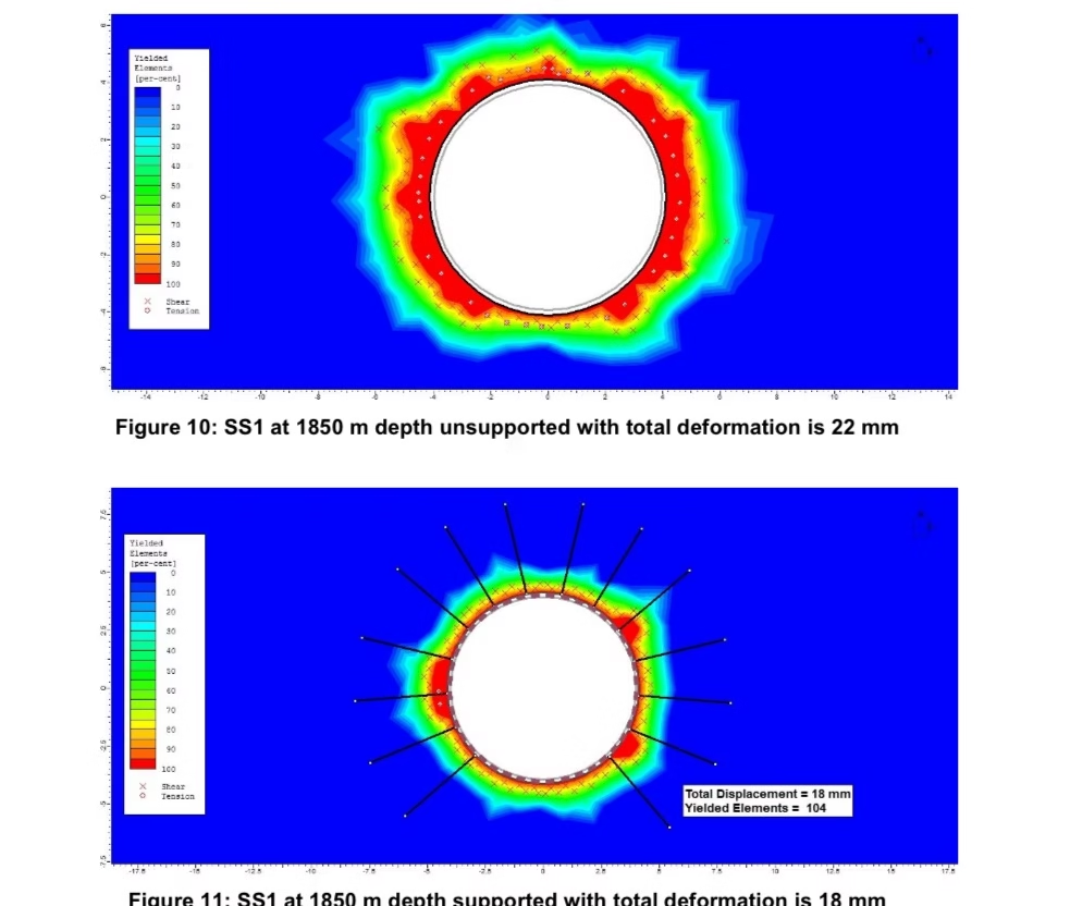
- SS1 (Sandstone): Stable with minimal radial displacement (16 mm) under 1,850 m rock cover using rock bolts and 100 mm of shotcrete.
- Mudstone: Exhibited maximum displacement (385 mm) and required heavy steel sets embedded in shotcrete to achieve stability.
2.2 Phase2 Modeling
Phase2 uses finite element analysis to simulate elasto-plastic behavior, providing a detailed understanding of rock mass deformation under stress. The program accounted for:
- Load splitting to simulate delayed support installation.
- Variable overburden levels (1,000 m, 1,300 m, 1,550 m, and 1,850 m).
The results highlighted that:
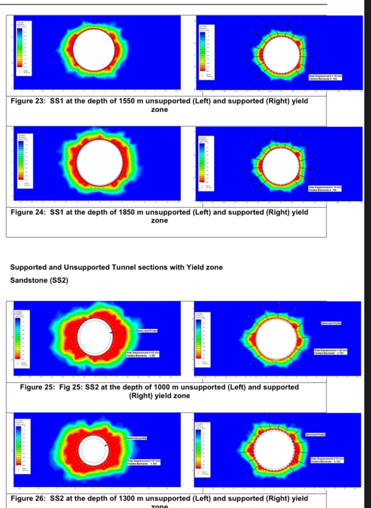
- Sandstone (SS1): Maintains structural integrity with minor radial displacement even at maximum depths.
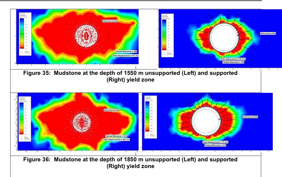
- Mudstone: Faces severe to very severe squeezing, necessitating early support installation and advanced techniques like face reinforcement.
3. Challenges in Tunnel Excavation
The excavation under high overburdens posed several challenges:
- High-Stress Zones: Increased tangential stresses led to spalling and stress slabbing, particularly in SS2 and mudstone-rich sequences.
- Squeezing Conditions: Severe squeezing occurred in mudstone, with strains exceeding 10%, necessitating heavy support installations.
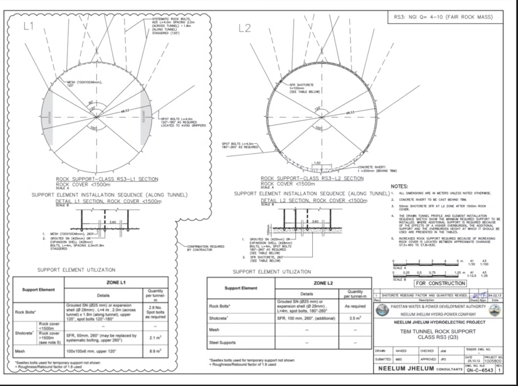
- Support Delays: The TBM design necessitated splitting support installation between the L1 (immediate) and L2 (delayed) sections, complicating logistics and stability.
4. Rock Support Design
The support system was tailored to each rock type and stress level to achieve equilibrium between ground reaction and support interaction.
4.1 Key Support Measures
- Shotcrete: Thickness ranged from 100 mm for SS1 to 300 mm for mudstone under maximum overburdens.
- Rock Bolts: 4 m long bolts, spaced variably from 2.5×2.5 m for SS1 to 1×1 m for mudstone.
- Steel Sets: I-beams and TH beams embedded in shotcrete were used for additional stability in highly stressed zones.
- Wire Mesh: Single-layer mesh ensured protection against rockfalls.
4.2 Rock-Specific Recommendations
- Sandstone (SS1): Requires minimal support, with 100-150 mm shotcrete and widely spaced rock bolts.
- Sandstone (SS2): Needs closer bolting (1.5×1.5 m) and additional support like light steel sets to achieve a safety factor of 1.5.
- Siltstone: Exhibits moderate squeezing; requires steel sets and 200-250 mm shotcrete for stability.
- Mudstone: Demands robust support, including heavy steel sets, 300 mm shotcrete, and face reinforcement techniques to mitigate extreme squeezing.
5. Quantification of Squeezing
The ratio of uniaxial compressive strength to in-situ stress serves as a key indicator for squeezing severity:
- Minor Squeezing: SS1 and SS2, with strains below 2.5%.
- Severe Squeezing: Siltstone, with strains up to 5%.
- Very Severe Squeezing: Mudstone, with strains exceeding 10%, requiring continuous monitoring and adaptive support strategies.
6. Innovations in Support Installation
The TBM design necessitated splitting support installation:
- L1 Section: Installed immediately behind the TBM shield (within 5 m of the face) to prevent deformation during excavation.
- L2 Section: Installed 50-55 m behind the face to optimize productivity.
Numerical modeling indicated that partial support in the L1 section must be robust enough to withstand full deformation before the L2 section installation.
7. Findings and Recommendations
7.1 Key Findings
- The behavior of rock masses varies significantly with depth, with mudstone requiring the most attention due to extreme squeezing.
- Numerical modeling validated empirical support designs while identifying the need for modifications under higher overburdens.
- Early and close-to-face support installation is crucial for mudstone to prevent collapse.
7.2 Recommendations
- Employ advanced monitoring systems to detect early signs of deformation.
- Adapt support designs dynamically based on real-time geological conditions.
- Ensure rigorous quality control during support installation, especially in high-stress zones.
8. Implications for Hydropower Projects
The insights gained from the Neelum-Jhelum project can be applied to similar hydropower ventures worldwide. Effective stress analysis and support design not only ensure the structural integrity of tunnels but also enhance worker safety and project efficiency.
Conclusion
The Neelum-Jhelum Hydroelectric Project exemplifies cutting-edge engineering in the field of tunnel excavation. By leveraging advanced numerical modeling tools like RocSupport and Phase2, the project successfully addressed the challenges of high overburdens and complex geology. The lessons learned underscore the importance of adaptive rock support design and continuous monitoring in ensuring the long-term stability of underground structures.
As hydropower projects continue to expand globally, the methodologies and findings from this project provide a robust framework for tackling similar challenges in future ventures.
